Introduction
TMS320F28069는 Texas Instruments의 C2000™ 시리즈 실시간 마이크로컨트롤러로, 모터 제어 및 고성능 모션/위치 제어 시스템에 적합한 기능을 제공합니다. 그중 Enhanced Quadrature Encoder Pulse (eQEP) 모듈은 증분형 쿼드러처 엔코더(Incremental Quadrature Encoder) 신호를 디코딩하여 회전 기계의 위치, 방향, 속도 정보를 얻는 데 사용됩니다.
The Enhanced Quadrature Encoder Pulse (EQEP) module is essential when integrating C2000 devices in any application that requires motor control. The EQEP module enables the C2000 device to interact with linear or rotary incremental encoders to determine necessary motor information from rotating machines.
What is an Incremental Quadrature Encoder?
증분형 구적 인코더란 무엇입니까
At a high-level, an incremental quadrature encoder is a digital angular position sensor. A generic incremental encoder is composed of a disk, a pair of optical sensors, and a light source. An incremental encoder disk is patterned with a track of slots (windows which allow light to pass through) around the periphery of the disk.
고차원에서 증분형 직교 인코더는 디지털 각위치 센서입니다. 일반적인 증분형 인코더는 디스크, 한 쌍의 광 센서, 그리고 광원으로 구성됩니다. 증분형 인코더 디스크는 디스크 주변에 슬롯(빛이 통과하는 창) 트랙이 패턴화되어 있습니다.

The optical sensors are positioned directly across from the light source on either side of this slotted track, and as the motor rotates, the sensors detect a pattern of light and dark lines. A light line is perceived when the optical sensor is positioned over a slot in the disk, and a dark line is perceived when the light source becomes obstructed by the disk.
The data perceived by these optical sensors are denoted by two channels, channel A and channel B, that are offset by some phase difference. The frequency of these signals and their phase difference can be used to calculate information such as the direction, speed, and position of the rotating motor.
광학 센서는 이 슬롯 트랙 양쪽의 광원 바로 맞은편에 위치하며, 모터가 회전함에 따라 센서는 밝은 선과 어두운 선의 패턴을 감지합니다. 광학 센서가 디스크의 슬롯 위에 위치하면 밝은 선이 감지되고, 광원이 디스크에 의해 가려지면 어두운 선이 감지됩니다.
이러한 광학 센서가 감지하는 데이터는 위상 차이에 의해 오프셋된 두 채널, 즉 채널 A와 채널 B로 표시됩니다. 이 신호의 주파수와 위상 차이는 회전 모터의 방향, 속도, 위치와 같은 정보를 계산하는 데 사용될 수 있습니다.
The incremental encoder disk may feature a second track with a single slot located at a fixed point. This second track can be used to produce an index signal which acts as a zero reference. This index signal, when fed into the EQEP peripheral, aids in motor positioning and pulse count verification. Because this index slot is positioned at a fixed point, this pulse occurs once per rotation and indicates to the device when a complete rotation has been made.
증분형 인코더 디스크에는 고정된 지점에 단일 슬롯이 있는 두 번째 트랙이 있을 수 있습니다. 이 두 번째 트랙은 원점 기준이 되는 인덱스 신호를 생성하는 데 사용될 수 있습니다. 이 인덱스 신호는 EQEP 주변 장치로 입력되면 모터 위치 결정 및 펄스 수 검증에 도움이 됩니다. 이 인덱스 슬롯은 고정된 지점에 위치하므로, 이 펄스는 회전당 한 번씩 발생하며, 장치에 회전이 완료되었음을 알려줍니다.
How is direction determined from quadrature signals?
직교 신호로부터 방향은 어떻게 결정됩니까
Quadrature signals carry valuable data that can be used to determine the direction of a motor’s rotation. The slots on a quadrature encoder are separated by a known angular difference θ, which results in the phase difference between pulse waveforms in channel A and B being fixed at θ/4 (90° offset). The channel A and B quadrature signals can be fed into the EQEP module, and the direction of motion can be decoded using a state machine.
직교 신호는 모터 회전 방향을 결정하는 데 사용할 수 있는 중요한 데이터를 전달합니다.
직교 인코더의 슬롯은 알려진 각도 차이 θ만큼 떨어져 있으며, 이로 인해 채널 A와 B의 펄스 파형 간 위상 차이는 θ/4(90° 오프셋)로 고정됩니다.
채널 A와 B의 직교 신호는 EQEP 모듈에 입력될 수 있으며, 상태 머신을 사용하여 동작 방향을 디코딩할 수 있습니다.
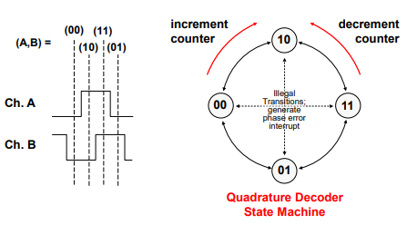
The state encodings represent the states of channels A and B at any point in time. 상태 인코딩은 특정 시점에서 채널 A와 B의 상태를 나타냅니다.
- when both channels are low, the encoding is (00) 두 채널 모두 낮을 때 인코딩은 (00)입니다
- when both channels are high, the encoding is (11) 두 채널 모두 높을 때 인코딩은 (11)입니다
- when channel A is high and channel B is low, the encoding is (10) 채널 A가 높고 채널 B가 낮을 때 인코딩은 (10)
- when channel A is low and channel B is high, the encoding is (01) 채널 A가 낮고 채널 B가 높을 때 인코딩은 (01)
Accordingly, the state transitions over one period uniquely encode the direction of rotation. For example, the state transitions (00,10,11,01) indicate a clockwise rotation, and the state transitions (01,11,10,00) indicate a counter-clockwise rotation.
따라서 한 주기 동안의 상태 전이는 회전 방향을 고유하게 인코딩합니다. 예를 들어, 상태 전이(00, 10, 11, 01)는 시계 방향 회전을 나타내고, 상태 전이(01, 11, 10, 00)는 반시계 방향 회전을 나타냅니다.
Because channels A and B are offset by a fixed phase difference θ/4, they cannot both change states simultaneously. This means that in the state machine, a direct transition from (00) to (11) or vice versa represents an illegal state change. The same is true between states (01) and (10).
채널 A와 B는 고정된 위상 차이 θ/4만큼 오프셋되어 있기 때문에 두 채널 모두 동시에 상태를 변경할 수 없습니다. 즉, 상태 머신에서 (00)에서 (11)로의 직접 전이 또는 그 반대로의 전이는 잘못된 상태 변경을 나타냅니다. 상태 (01)과 (10) 사이에서도 마찬가지입니다.
How is angular position and velocity determined from quadrature signals?
각위치와 각속도는 어떻게 직교신호로부터 결정되나요
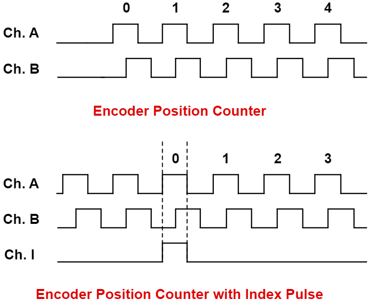
The angular position of the incremental encoder can be determined in multiple ways depending on the design of the encoder. The EQEP module has a counter which keeps track of the number of pulses coming in from channels A and B.
증분형 인코더의 각도 위치는 인코더 설계에 따라 여러 가지 방법으로 결정될 수 있습니다. EQEP 모듈에는 채널 A와 B에서 들어오는 펄스 수를 추적하는 카운터가 있습니다. 시계 방향으로 움직이면 카운터가 증가하고, 시계 반대 방향으로 움직이면 카운터가 감소합니다.
A clockwise movement results in an increment of the counter and a counter-clockwise movement results in a decrement.
The number of slots in an incremental quadrature encoder, referred to as the resolution of the encoder, is equivalent to the number of pulses in a single rotation. The number of pulses in a single rotation is denoted by PPR (pulses per rotation). Hence, the angular position of the rotary encoder is stored in the counter, incrementing and decrementing depending on the rotation of the motor.
증분형 직교 인코더의 슬롯 수, 즉 인코더의 분해능은 1회전당 펄스 수와 같습니다. 1회전당 펄스 수는 PPR(pulse per rotation)로 표시합니다. 따라서 회전 인코더의 각 위치는 카운터에 저장되며, 모터 회전에 따라 증가하거나 감소합니다.
If the quadrature encoder contains an index pulse, the position of the encoder can be found by comparing the counter value to the counter value at the previous index pulse. Alternately, the index can be used to verify the value of the encoder counter value and the angular position.
직교 인코더에 인덱스 펄스가 포함된 경우, 카운터 값을 이전 인덱스 펄스의 카운터 값과 비교하여 인코더의 위치를 찾을 수 있습니다. 또는 인덱스를 사용하여 인코더 카운터 값과 각 위치를 확인할 수 있습니다.
For every revolution of the encoder disk, there is typically one revolution of the motor. Thus, the frequency of the channel A and B pulses is directly proportional to the velocity of the motor. This relation is described by the following equation:
인코더 디스크가 한 바퀴 회전할 때마다 일반적으로 모터도 한 바퀴 회전합니다. 따라서 채널 A와 B 펄스의 주파수는 모터의 속도에 정비례합니다. 이 관계는 다음 방정식으로 표현됩니다.
For example, a 1000-slot incremental encoder coupled to a motor running at 5000 revolutions per minute (RPM) results in channel A and B pulsing at a frequency of 300 kHz. Thus, the angular velocity can be calculated by measuring the time it takes for an arbitrary number of pulses to occur.
예를 들어, 분당 회전수(RPM)가 5,000인 모터에 1,000슬롯 증분형 인코더를 연결하면 채널 A와 B가 300kHz의 주파수로 펄스를 발생시킵니다. 따라서 각속도는 임의의 펄스 수가 발생하는 데 걸리는 시간을 측정하여 계산할 수 있습니다.
Applications of the EQEP Module EQEP 모듈의 응용 프로그램
The EQEP module on C2000 devices is responsible for decoding the pulse signals from incremental quadrature encoders, and is used specifically in high-performance motion and position-control systems. It is typically used as part of a control interface for tight loop motor controls in motor control applications for industrial and automotive end equipment.
C2000 장치의 EQEP 모듈은 증분형 직교 인코더의 펄스 신호를 디코딩하는 역할을 하며, 특히 고성능 모션 및 위치 제어 시스템에 사용됩니다. 이 모듈은 일반적으로 산업 및 자동차용 최종 장비의 모터 제어 애플리케이션에서 타이트 루프 모터 제어를 위한 제어 인터페이스의 일부로 사용됩니다. EQEP 모듈은 직교 인코더의 위치, 방향 및 속도를 결정하는 데 사용할 수 있습니다. 또한 내부 위치 카운터를 통해 EQEP 모듈은 입력 신호의 펄스 수를 계산할 수 있습니다.
The EQEP module can be used to determine the position, direction, and speed of quadrature encoders. The internal position counter also enables the EQEP module to be able to keep count of the number of pulses from the input signals.
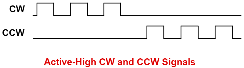
The EQEP works directly with pulse train output (PTO) module signals, which are primarily utilized in position controllers. A PTO module issues pulses to a motor which directly rotates the shaft of the motor and thus has direct control over the motor. Common types of PTO signals include clockwise (CW) and counter-clockwise (CCW) pulses. Each pulse corresponds to a fractional rotation, where CW indicates a positive increment and CCW indicates a negative increment. CW/CCW signals can function in active-high or active-low. Active-high CW/CCW signals realize motor movements when the CW or CCW signals go high, and active-low signals realize movements when the signals are brought low.
EQEP는 주로 위치 제어기에 사용되는 펄스열 출력(PTO) 모듈 신호와 직접 연동합니다. PTO 모듈은 모터에 펄스를 전달하고, 모터는 모터 축을 직접 회전시켜 모터를 직접 제어합니다. 일반적인 PTO 신호 유형으로는 시계 방향(CW) 및 반시계 방향(CCW) 펄스가 있습니다. 각 펄스는 분수 회전에 해당하며, CW는 양의 값, CCW는 음의 값을 나타냅니다. CW/CCW 신호는 액티브 하이(Active High) 또는 액티브 로우(Active Low)로 동작할 수 있습니다. 액티브 하이 CW/CCW 신호는 CW 또는 CCW 신호가 하이(High)가 되면 모터의 움직임을 구현하고, 액티브 로우 신호는 신호가 로우(Low)가 되면 움직임을 구현합니다.
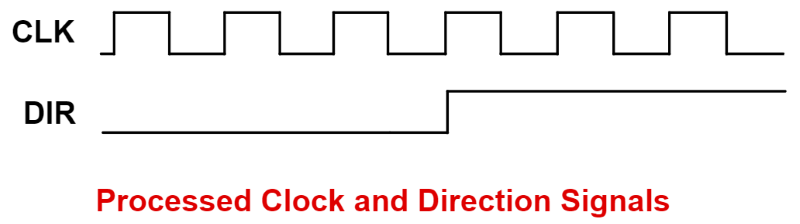
These PTO signals can be directly driven into the EQEP module. The EQEP module converts them directly into direction and clock signals, which the C2000 chip further produces into pulse-width modulation (PWM) signals intended to drive motors.
이러한 PTO 신호는 EQEP 모듈로 직접 전달될 수 있습니다. EQEP 모듈은 이 신호를 방향 및 클록 신호로 직접 변환하고, C2000 칩은 이를 모터 구동을 위한 펄스 폭 변조(PWM) 신호로 생성합니다.
The EQEP module may also function as a 16-bit capture unit in applications where additional capture units are required beyond the dedicated eCAP modules provided on these microcontrollers. Each EQEP module features an edge-capture unit (discussed in detail further) which, in typical motor applications, aids in providing accurate estimates for low speed measurements. This capture submodule enables the EQEP module to serve as a general-purpose capture unit.
EQEP 모듈은 이러한 마이크로컨트롤러에 제공되는 전용 eCAP 모듈 외에 추가 캡처 유닛이 필요한 애플리케이션에서 16비트 캡처 유닛으로도 작동할 수 있습니다. 각 EQEP 모듈은 에지 캡처 유닛(추후 자세히 설명)을 갖추고 있으며, 이는 일반적인 모터 애플리케이션에서 저속 측정에 대한 정확한 추정치를 제공하는 데 도움이 됩니다. 이 캡처 서브모듈을 통해 EQEP 모듈은 범용 캡처 유닛으로 사용할 수 있습니다.
EQEP Block Diagram EQEP 블록 다이어그램
The figure below shows a summary of the connections to the EQEP module.

The inputs include two pins (EQEPxA/QEPA and EQEPxB/QEPB) for quadrature-clock mode or direction-count mode, an index pin (EQEPxI/QEPI), and a strobe pin (EQEPxS/QEPS). These pins are configured using the GPIO multiplexer and need to be enabled for synchronous input.
입력에는 직교 클럭 모드 또는 방향 카운트 모드를 위한 두 개의 핀(EQEPxA/QEPA 및 EQEPxB/QEPB), 인덱스 핀(EQEPxI/QEPI), 그리고 스트로브 핀(EQEPxS/QEPS)이 포함됩니다. 이 핀들은 GPIO 멀티플렉서를 사용하여 구성되며 동기 입력을 위해 활성화되어야 합니다.
In quadrature-clock mode, two square wave signals from a position encoder are inputs to QEPA and QEPB which are 90 electrical degrees out of phase. This phase relationship is used to determine the direction of rotation. If the position encoder provides direction and clock outputs, instead of quadrature outputs, direction-count mode can be used. QEPA input will provide the clock signal (XCLK) and QEPB input will have the direction information (XDIR).
직교 클록 모드에서는 위치 인코더에서 생성된 두 개의 구형파 신호가 QEPA와 QEPB에 입력되며, 두 신호는 전기적으로 90도 위상 차이가 납니다. 이 위상 관계는 회전 방향을 결정하는 데 사용됩니다. 위치 인코더가 직교 출력 대신 방향 및 클록 출력을 제공하는 경우, 방향 카운트 모드를 사용할 수 있습니다. QEPA 입력은 클록 신호(XCLK)를 제공하고 QEPB 입력은 방향 정보(XDIR)를 제공합니다.
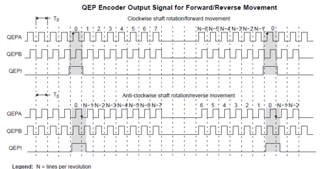
The QEPI index signal occurs once per revolution and can be used to indicate an absolute start position from which position information is incrementally encoded using quadrature pulses. The QEPS strobe signal can be connected to a sensor or limit switch to indicate that a defined position has been reached.
QEPI 인덱스 신호는 회전당 한 번 발생하며, 절대 시작 위치를 나타내는 데 사용할 수 있으며, 이 시작 위치로부터 위치 정보가 직교 펄스를 사용하여 점진적으로 인코딩됩니다. QEPS 스트로브 신호는 센서 또는 리미트 스위치에 연결되어 지정된 위치에 도달했음을 나타낼 수 있습니다.
EQEP Functional Units EQEP 기능 단위
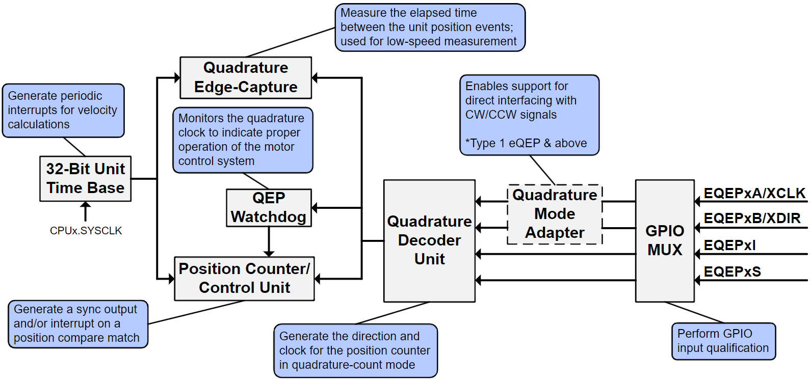
The EQEP peripheral contains a number of major functional units:
- Programmable input qualification for each pin (part of the GPIO MUX)
- Quadrature decoder unit (QDU)
- Position counter and control unit for position measurement (PCCU)
- Quadrature edge-capture unit for low-speed measurement (QCAP)
- Unit time base for speed/frequency measurement (UTIME)
- Watchdog timer for detecting stalls (QWDOG)
- Quadrature Mode Adapter (QMA)
EQEP 주변 장치에는 여러 가지 주요 기능 장치가 포함되어 있습니다.
- 각 핀에 대한 프로그래밍 가능한 입력 자격(GPIO MUX의 일부)
- 구적 디코더 유닛(QDU)
- 위치 측정을 위한 위치 카운터 및 제어 장치(PCCU)
- 저속 측정을 위한 사분면 에지 캡처 장치(QCAP)
- 속도/주파수 측정을 위한 단위 시간 기준(UTIME)
- 정지 감지용 워치독 타이머(QWDOG)
- 쿼드러처 모드 어댑터(QMA)
The diagram below shows a high-level block diagram of the EQEP module and its major functional units on C2000 devices. 아래 다이어그램은 C2000 장치에서 EQEP 모듈과 주요 기능 단위의 상위 레벨 블록 다이어그램을 보여줍니다.
GPIO MUX Input Qualification GPIO MUX 입력 자격
Inputs into the EQEP module (EQEPxA, EQEPxB, EQEPxI, EQEPxS) can undergo GPIO input qualification before they are fed into the EQEP module. In instances where potential noise may distort the EQEP input signals, input qualification can aid in making the inputs more immune to noise, resulting in more stable speed and position measurement. The input qualification sampling period and type of qualification can be individually configured.
EQEP 모듈로의 입력(EQEPxA, EQEPxB, EQEPxI, EQEPxS)은 EQEP 모듈로 입력되기 전에 GPIO 입력 검증을 거칠 수 있습니다. 잠재적인 노이즈로 인해 EQEP 입력 신호가 왜곡될 수 있는 경우, 입력 검증을 통해 입력 신호의 노이즈 영향을 줄여 더욱 안정적인 속도 및 위치 측정을 얻을 수 있습니다. 입력 검증 샘플링 주기와 검증 유형은 개별적으로 설정할 수 있습니다
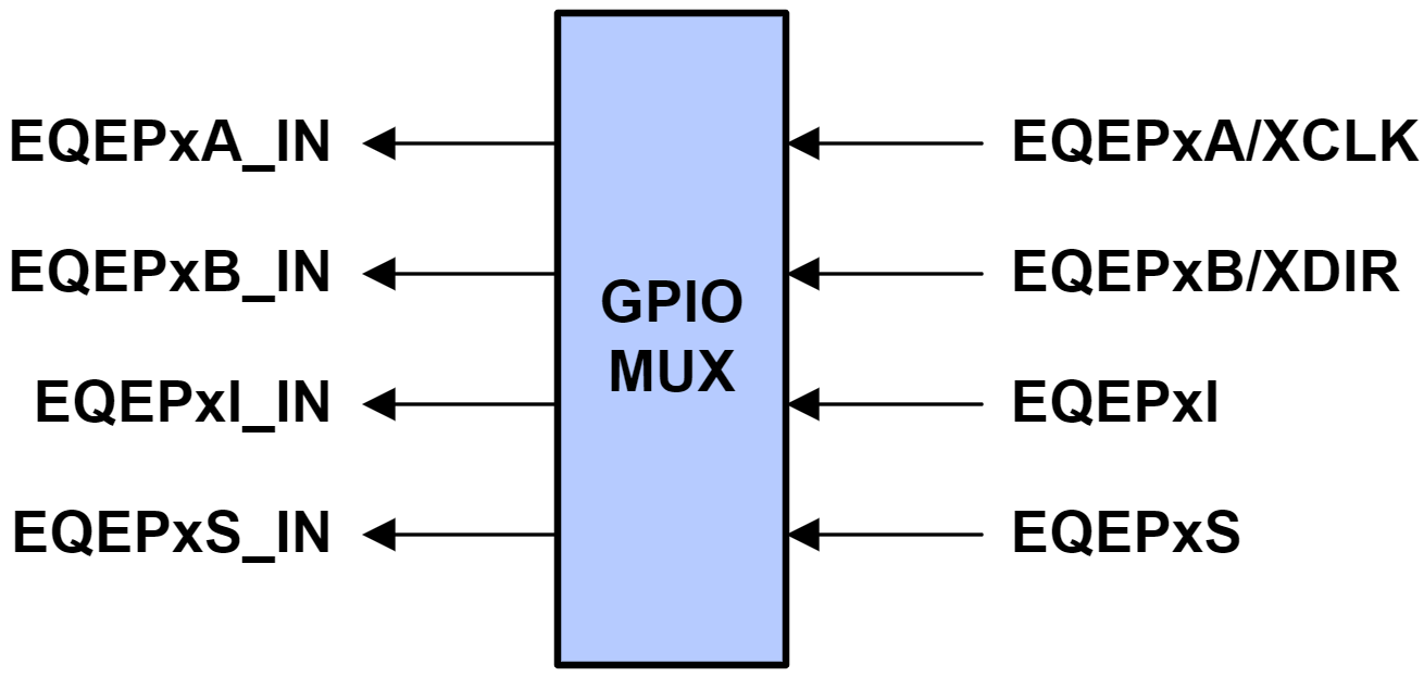
Outputs of the GPIO MUX block (EQEPxA_IN, EQEPxB_IN, EQEPxI_IN, EQEPxS_IN) are connected to the QMA (on applicable devices) and the QDU.
GPIO MUX 블록의 출력(EQEPxA_IN, EQEPxB_IN, EQEPxI_IN, EQEPxS_IN)은 QMA(해당 장치의 경우)와 QDU에 연결됩니다.
Quadrature Decoder Unit (QDU)
The Quadrature Decoder Unit is the primary functional unit within the EQEP module which allows for motor control measurement. It is responsible for generating clock (QCLK) and direction (QDIR) signals which are fed into the rest of the EQEP module (e.g., position counter and control unit, edge-capture unit, etc.)
직교 디코더 유닛 은 EQEP 모듈 내의 주요 기능 유닛으로, 모터 제어 측정을 가능하게 합니다. 이 유닛은 클록(QCLK) 및 방향(QDIR) 신호를 생성하여 EQEP 모듈의 나머지 부분(예: 위치 카운터 및 제어 유닛, 에지 캡처 유닛 등)으로 전달합니다.
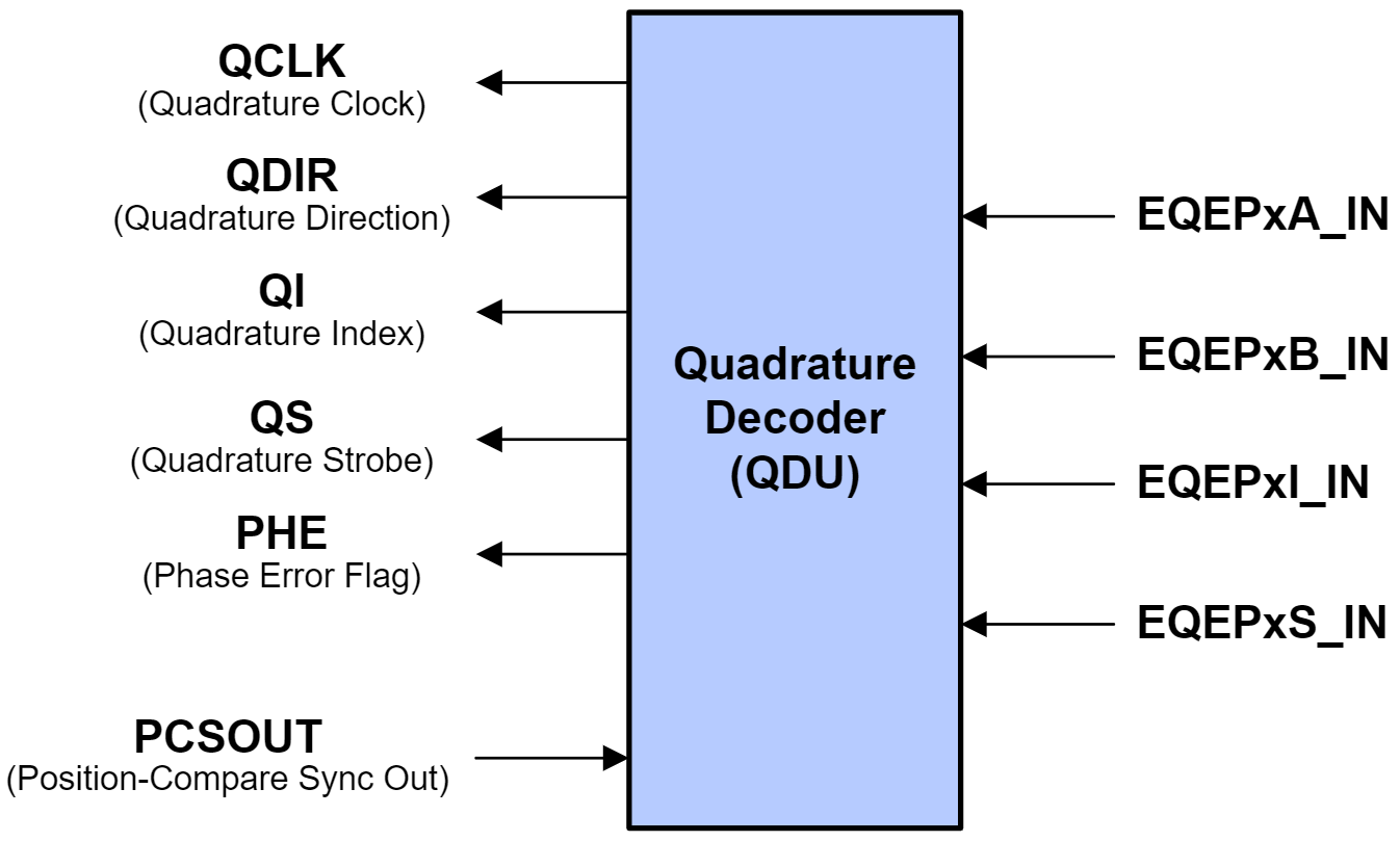
There are 4 input modes which determine the clock and direction inputs into the position counter. These are Quadrature-Count mode, Direction-Count mode, Up-Count mode, and Down-count mode.
위치 카운터에 대한 클록 및 방향 입력을 결정하는 4가지 입력 모드가 있습니다. 직교 카운트 모드, 방향 카운트 모드, 상향 카운트 모드, 하향 카운트 모드입니다.
In Quadrature-Count mode, the quadrature decoder generates the direction and clock signals from quadrature inputs QEPA, QEPB, and QEPI. The quadrature decoder uses direction decoding logic to determine the leading signal between QEPA and QEPB. The direction of movement is then fed into other functional units. Note that because the quadrature decoder samples both edges of inputs QEPA and QEPB, the generated QCLK freqency is four times the frequency of the input sequence.
직교 카운트 모드 에서 직교 디코더는 직교 입력 QEPA, QEPB, QEPI로부터 방향 신호와 클록 신호를 생성합니다. 직교 디코더는 방향 디코딩 로직을 사용하여 QEPA와 QEPB 사이의 선행 신호를 결정합니다. 이동 방향은 다른 기능 유닛으로 전달됩니다. 직교 디코더는 입력 QEPA와 QEPB의 양쪽 에지를 모두 샘플링하므로, 생성된 QCLK 주파수는 입력 시퀀스 주파수의 4배입니다.
Direction-Count mode is intended for use with encoders that provide direction and clock outputs as opposed to quadrature outputs. In this mode, QEPA will provide the clock signal (XCLK), and QEPB will provide the direction information (XDIR). The position counter is incremented on every QEPA rising edge when direction (QEPB) is high and decremented when the direction is low.
방향-카운트 모드는 직교 출력이 아닌 방향 및 클럭 출력을 제공하는 인코더와 함께 사용하도록 설계되었습니다. 이 모드에서 QEPA는 클럭 신호(XCLK)를 제공하고 QEPB는 방향 정보(XDIR)를 제공합니다. 위치 카운터는 방향(QEPB)이 High일 때 QEPA의 모든 상승 에지에서 증가하고, 방향이 Low일 때 감소합니다.
In Up-Count mode and Down-Count mode, the counter direction is always hard-wired high for up-count mode or low for down-count mode. The position counter is then used to measure the frequency of the QEPA input. In these modes, the QDU unit can be configured to generate clock events on both rising and falling edges of the QEPA input, essentially doubling the measurement resolution.
업 카운트 모드 와 다운 카운트 모드 에서 카운터 방향은 업 카운트 모드에서는 항상 하이(High)로, 다운 카운트 모드에서는 로우(Low)로 하드와이어링됩니다. 위치 카운터는 QEPA 입력의 주파수를 측정하는 데 사용됩니다. 이러한 모드에서 QDU 유닛은 QEPA 입력의 상승 및 하강 에지 모두에서 클럭 이벤트를 생성하도록 구성될 수 있으며, 이를 통해 측정 분해능이 두 배로 향상됩니다.
The inputs into the EQEP are validated and can be manipulated through software. When an invalid quadrature transition occurs (as described in How is direction determined from quadrature signals?) a phase error flag (PHE) will be set within the QDU. Each EQEP input can be inverted prior to being input into the quadrature decoder. Optionally, inputs QEPA and QEPB can be swapped through software, resulting in the counting direction being reversed.
EQEP 입력은 검증되며 소프트웨어를 통해 조작할 수 있습니다. 유효하지 않은 직교 전이가 발생하면("직교 신호에서 방향은 어떻게 결정되는가?"에서 설명한 대로), QDU 내에 위상 오류 플래그(PHE)가 설정됩니다. 각 EQEP 입력은 직교 디코더에 입력되기 전에 반전될 수 있습니다. 선택적으로, 소프트웨어를 통해 입력 QEPA와 QEPB를 서로 바꿔서 계산 방향을 반전할 수 있습니다.
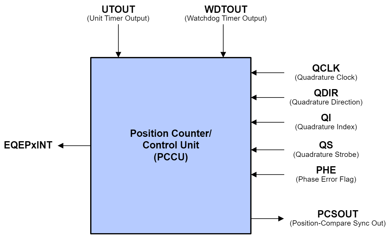
Position Counter and Control Unit (PCCU) 위치 카운터 및 제어 장치
The Position Counter and Control Unit is responsible for keeping count of the encoder pulses being received by the EQEP module.
위치 카운터 및 제어 장치는 EQEP 모듈이 수신하는 인코더 펄스의 수를 계산하는 역할을 합니다.
The QCLK and QDIR signals being output from the quadrature decoder unit are received by the position counter. The position counter counts the number of QCLK pulses for a particular direction in a specified period of time. The value of the position counter is directly related to the number of encoder pulses in that period. The frequency of the input signals can then be calculated, which in turn allows for the calculation of the position and speed.
직교 디코더 유닛에서 출력되는 QCLK 및 QDIR 신호는 위치 카운터에 수신됩니다. 위치 카운터는 지정된 시간 동안 특정 방향에 대한 QCLK 펄스 수를 계산합니다. 위치 카운터의 값은 해당 시간 동안의 인코더 펄스 수와 직접적인 관련이 있습니다. 그러면 입력 신호의 주파수를 계산할 수 있으며, 이를 통해 위치와 속도를 계산할 수 있습니다.
By adjusting the signal or event that resets the position counter, the position counter can be used to record the total number of encoder pulses received, to document only the encoder position in the current motor revolution, or to perform another custom function. Four different modes are available, which include:
위치 카운터를 재설정하는 신호 또는 이벤트를 조정하면, 위치 카운터를 사용하여 수신된 총 인코더 펄스 수를 기록하거나, 현재 모터 회전에서 인코더 위치만 기록하거나, 다른 사용자 지정 기능을 수행할 수 있습니다. 다음과 같은 네 가지 모드를 사용할 수 있습니다.
- Position-Counter Reset on Index Event
- Position-Counter Reset on Maximum Position
- Position-Counter Reset on the first Index Event
- Position-Counter Reset on Unit Time Out Event (Frequency Measurement)
· 인덱스 이벤트 시 위치 카운터 재설정
· 최대 위치에서 위치 카운터 재설정
· 첫 번째 인덱스 이벤트에서 위치 카운터 재설정
· 유닛 시간 초과 이벤트 시 위치 카운터 재설정(주파수 측정)
The position counter has a max configurable position value which determines the upper limit of the position counter. Regardless of the mode, when a reset condition has been met, the position counter will reset to 0 if the reset occurs during forward movement. If the reset occurs during reverse movement, the position counter will be reset to the maximum position counter value.
위치 카운터에는 설정 가능한 최대 위치 값이 있으며, 이 값이 위치 카운터의 상한을 결정합니다. 모드와 관계없이, 리셋 조건이 충족되면 정방향 이동 중에 리셋이 발생하면 위치 카운터는 0으로 리셋됩니다. 역방향 이동 중에 리셋이 발생하면 위치 카운터는 최대 위치 카운터 값으로 리셋됩니다.
The EQEP module can be configured to latch the position value when a specified event occurs on the index and strobe inputs.
EQEP 모듈은 인덱스 및 스트로브 입력에서 지정된 이벤트가 발생하면 위치 값을 래치하도록 구성할 수 있습니다.
Latching on an index event can be useful in applications which want to utilize position counter error checking and whereby the position counter is not configured to reset on the index event. In these applications, the position counter keeps track of the number of encoder pulses over multiple motor revolutions. By latching on index events, it is possible to verify whether or not the position counter accumulated the correct number of counts between index events. For example, in a 1000-line encoder, the expected count difference after one full rotation should be 4000.
인덱스 이벤트 래칭은 위치 카운터 오류 검사를 활용하고 위치 카운터가 인덱스 이벤트에서 재설정되도록 구성되지 않은 애플리케이션에서 유용할 수 있습니다 . 이러한 애플리케이션에서 위치 카운터는 여러 모터 회전에 걸쳐 인코더 펄스 수를 추적합니다. 인덱스 이벤트 래칭을 통해 위치 카운터가 인덱스 이벤트 간에 정확한 카운트 수를 누적했는지 확인할 수 있습니다. 예를 들어, 1000라인 인코더의 경우, 1회전 후 예상되는 카운트 차이는 4000이어야 합니다.
The position counter can be configured to initialize to a specific value upon an index event, a strobe event, or through software initialization.
위치 카운터는 인덱스 이벤트, 스트로브 이벤트 또는 소프트웨어 초기화를 통해 특정 값으로 초기화되도록 구성할 수 있습니다.
The EQEP peripheral contains a position-compare unit which can be used to generate sync outputs and/or interrupts on position-compare events. This unit has support for shadow mode, where the shadow values are loaded during a compare match or a position counter zero event.
EQEP 주변 장치에는 위치 비교 이벤트 시 동기 출력 및/또는 인터럽트를 생성하는 데 사용할 수 있는 위치 비교 장치가 포함되어 있습니다. 이 장치는 비교 일치 또는 위치 카운터 제로 이벤트 중에 섀도 값이 로드되는 섀도 모드를 지원합니다.
Quadrature Edge-Capture Unit (QCAP) 사분면 에지 캡처 장치
The Quadrature Edge-Capture Unit is included in the EQEP module for accurate low-speed measurements. This functional unit features an internal 16-bit capture timer that is derived from the prescaled system clock (SYSCLKOUT) and a 4-bit binary divider, which is used to generate unit position events from the QCLK signal.
직교 에지 캡처 유닛은 정확한 저속 측정을 위해 EQEP 모듈에 포함되어 있습니다. 이 기능 유닛은 사전 스케일링된 시스템 클록(SYSCLKOUT)에서 파생된 내부 16비트 캡처 타이머와 QCLK 신호로부터 유닛 위치 이벤트를 생성하는 데 사용되는 4비트 이진 분할기를 갖추고 있습니다.
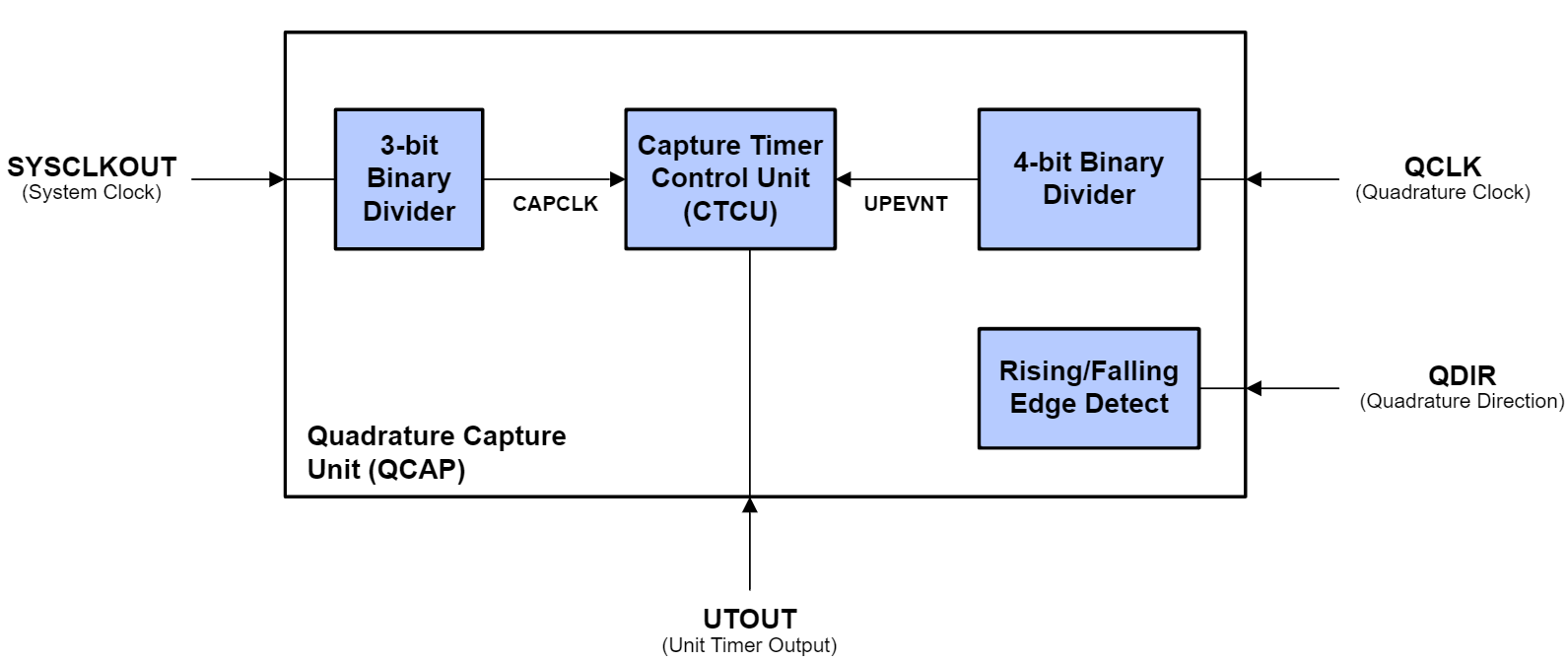
On every unit position event, the value of the capture timer is stored, and the capture timer is reset. The QCAP unit measures the elapsed time between unit position events and can use this information to calculate the velocity of the motor. This is described below in the following equation:
모든 유닛 위치 이벤트 발생 시, 캡처 타이머의 값이 저장되고 캡처 타이머는 재설정됩니다. QCAP 유닛은 유닛 위치 이벤트 간의 경과 시간을 측정하고 이 정보를 사용하여 모터의 속도를 계산합니다. 이는 아래 방정식에 설명되어 있습니다.
- X defines the unit position X는 단위 위치를 정의합니다.·
- ΔT defines the elapsed time between unit position events ΔT는 단위 위치 이벤트 사이의 경과 시간을 정의합니다.
- v(k) describes the velocity at time k. v(k)는 시간 k 에서의 속도를 나타냅니다 .
The low-speed measurement is accurate as long as the capture timer does not overflow (period between unit position events must be less than 65,535) and there is no change in direction. Relevant error flags will be thrown when these conditions are not met.
저속 측정은 캡처 타이머가 오버플로우되지 않고(유닛 위치 이벤트 간격이 65,535 미만이어야 함) 방향 변화가 없는 한 정확합니다. 이러한 조건이 충족되지 않으면 관련 오류 플래그가 발생합니다.
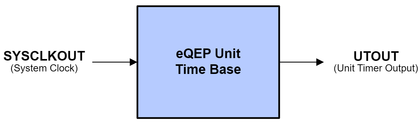
Unit Time Base (UTIME) 단위 시간 기준
The Unit Time Base is responsible for issuing period interrupts to the CPU for velocity calculations. These interrupts are clocked by a 32-bit unit timer, and the frequency of interrupts can be manually configured. This functional unit can also be configured to capture the position counter, capture timer, and capture period values on interrupt. These values can then be used for QCAP velocity calculation.
단위 시간 기준(Unit Time Base)은 속도 계산을 위해 CPU에 주기 인터럽트를 발생시키는 역할을 합니다. 이러한 인터럽트는 32비트 단위 타이머에 의해 클록되며, 인터럽트 발생 빈도는 수동으로 설정할 수 있습니다. 또한, 이 기능 단위는 인터럽트 발생 시 위치 카운터, 타이머, 그리고 주기 값을 캡처하도록 설정할 수 있습니다. 이러한 값들은 QCAP 속도 계산에 사용될 수 있습니다.
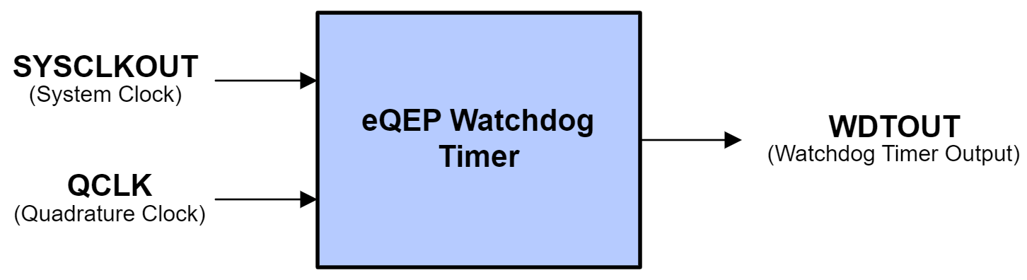
Watchdog Timer (QWDOG) 워치독 타이머
The EQEP module is able to detect potential stalls and issue fault flags using the integrated Watchdog Timer. A time-out duration value can be configured within the QWDOG. When no quadrature clock events are detected in a time period such that the watchdog timer exceeds the time-out duration, the watchdog will issue an interrupt flag.
EQEP 모듈은 내장된 워치독 타이머를 사용하여 잠재적인 정지를 감지하고 오류 플래그를 생성할 수 있습니다 . QWDOG 내에서 타임아웃 지속 시간을 설정할 수 있습니다. 특정 시간 동안 직교 클럭 이벤트가 감지되지 않아 워치독 타이머가 타임아웃 지속 시간을 초과하면 워치독은 인터럽트 플래그를 생성합니다.
Quadrature Mode Adapter (QMA)
QMA Only on EQEP Type 1 and Above EQEP 유형 1 또는 그 이상에서만 QMA 가능
The Quadrature Mode Adapter unit is available only on device families with EQEP Type 1 or later. Refer to the C2000 Real-Time Control MCU Peripherals Reference Guide for more information on EQEP types.
Quadrature Mode Adapter 장치는 EQEP Type 1 이상을 지원하는 장치 제품군에서만 사용할 수 있습니다. EQEP 유형에 대한 자세한 내용은 C2000 실시간 제어 MCU 주변 장치 참조 가이드를 참조하십시오.
The EQEP module features two additional modes of operation which support direct interfacing with CW/CCW signals. The Quadrature Mode Adapter enables support for these modes and alters the QEPA and QEPB inputs before they are fed into the rest of the EQEP module. The QMA module receives CW/CCW signals and converts them to clock and direction signals which can then be used by the EQEP module. It also incorporates error detection logic to detect illegal transitions on the QEPA and QEPB inputs.
EQEP 모듈은 CW/CCW 신호와의 직접 인터페이싱을 지원하는 두 가지 추가 작동 모드를 제공합니다. 직교 모드 어댑터는 이러한 모드를 지원하고 QEPA 및 QEPB 입력을 EQEP 모듈의 나머지 부분으로 전송하기 전에 변경합니다. QMA 모듈은 CW/CCW 신호를 수신하여 EQEP 모듈에서 사용할 수 있는 클록 및 방향 신호로 변환합니다. 또한 QEPA 및 QEPB 입력에서 잘못된 전이를 감지하는 오류 감지 로직을 내장하고 있습니다.

By default (QMA Mode 0), the QMA is bypassed and QEPA and QEPB have a direct connection from the pins to the EQEP module. To utilize the Quadrature Mode Adapter unit, QMA Mode 1 or QMA Mode 2 must be enabled and the Quadrature Decoder Unit configured to function in Direction-Count mode.
기본적으로(QMA 모드 0) QMA는 우회되며 QEPA와 QEPB는 핀에서 EQEP 모듈로 직접 연결됩니다. 직교 모드 어댑터 장치를 사용하려면 QMA 모드 1 또는 QMA 모드 2를 활성화하고 직교 디코더 장치가 방향 카운트 모드에서 작동하도록 구성해야 합니다.
QMA Mode 1 is intended for use when the EQEP is receiving active-low CW/CCW signals. QMA Mode 2 is intended for use when the EQEP is receiving active-high CW/CCW signals.
QMA 모드 1은 EQEP가 액티브 로우 CW/CCW 신호를 수신할 때 사용하도록 설계되었습니다. QMA 모드 2는 EQEP가 액티브 하이 CW/CCW 신호를 수신할 때 사용하도록 설계되었습니다.
=============================
1. eQEP 모듈의 역할
- 기능: eQEP 모듈은 선형 또는 회전형 증분형 쿼드러처 엔코더와 직접 인터페이스하여 모터의 위치, 방향, 속도를 계산합니다. 이는 고성능 모션 제어 시스템에서 필수적입니다.
- 적용 사례: 모터 제어(예: 서보 모터, DC 모터), 로봇 공학, 산업 자동화 등에서 사용됩니다.
- 주요 입력 신호:
- Channel A (QEPxA) 및 Channel B (QEPxB): 쿼드러처 신호로, 엔코더 디스크의 회전에 따라 펄스를 생성하며, 두 신호의 위상 차이를 통해 회전 방향을 결정합니다.
- Index (QEPxI): 엔코더 디스크의 특정 위치(제로 참조점)에서 한 번 발생하는 신호로, 절대 위치 기준을 제공합니다.
- Strobe (QEPxS): 추가적인 위치 참조 신호로, 일부 애플리케이션에서 사용됩니다.
2. TMS320F28069의 eQEP 사양
- 모듈 수: TMS320F28069는 최대 2개의 eQEP 모듈을 지원합니다.
- 주요 기능:
- 쿼드러처 카운트 모드: Channel A와 B 신호를 사용하여 위치와 방향을 추적합니다.
- 위치 카운터: 엔코더의 펄스를 카운트하여 모터의 상대적 위치를 계산합니다.
- 단위 시간 이벤트(Unit Time Event): 주기적인 인터럽트를 발생시켜 속도 계산을 지원합니다.
- 속도 계산: 펄스 주기와 위상 차이를 통해 회전 속도를 측정합니다.
- 캡처 유닛(Capture Unit): 저속 동작에서도 정확한 타이밍 측정을 위해 SYSCLKOUT을 프리스케일링하여 사용합니다. 예를 들어, 최대 65535 카운트까지 처리 가능하며, 오버플로우 발생 시 속도를 0으로 간주하고 카운터를 재설정할 수 있습니다.
- 클럭 프리스케일링: SYSCLK(90MHz)을 최대 1/128로 분주하여 저속 동작에서 오버플로우를 관리합니다. 예를 들어, 90MHz에서 1/128 분주 시 약 93ms 동안 카운트 가능.
3. 동작 원리
- 증분형 쿼드러처 엔코더: 엔코더 디스크에 슬롯이 패턴화되어 있으며, 광학 센서가 슬롯을 통해 빛을 감지하여 펄스를 생성합니다. Channel A와 B는 위상 차(90도)를 가지며, 이를 통해 방향을 판단합니다. Index 신호는 한 바퀴 회전 시 기준점 역할을 합니다.
- 방향 판단: Channel A가 B를 앞서면 정방향, B가 A를 앞서면 역방향으로 판단합니다.
- 속도 및 위치 계산:
- 위치: 펄스 카운트를 통해 상대적 위치를 추적.
- 속도: 단위 시간당 펄스 수 또는 펄스 간 타이밍을 통해 계산.
- 인터럽트: 단위 시간 이벤트나 인덱스 이벤트를 통해 CPU에 주기적인 업데이트를 제공합니다.
4. 설정 및 사용
- 구성: eQEP 모듈은 쿼드러처 카운트 모드로 설정되며, Channel A, B, Index 신호를 GPIO 핀에 연결합니다. 예를 들어, TMS320F28069의 GPIO MUX를 통해 QEPxAIN, QEPxBIN, QEPxIIN 핀을 설정합니다.
- 프로그래밍:
- Texas Instruments의 C2000Ware에서 제공하는 소프트웨어 라이브러리와 예제를 활용하여 eQEP 모듈을 초기화하고 설정할 수 있습니다.
- C2000 Academy의 eQEP 랩에서는 1000라인 쿼드러처 엔코더를 예로 들어 위치와 속도를 계산하는 방법을 제공합니다.
- 예제 애플리케이션: PWM 신호를 사용하여 모터를 구동하고, eQEP 모듈로 엔코더 신호를 읽어 모터의 특성을 분석합니다.
5. 주의사항
- 저속 동작 시 오버플로우: 저속 모터 동작에서 캡처 카운터가 오버플로우할 가능성이 있습니다. 이 경우, 속도를 0으로 간주하고 카운터를 재설정하는 로직을 구현할 수 있습니다.
- 엔코더 선택: 광학 또는 자기식 쿼드러처 엔코더를 선택할 수 있으며, 애플리케이션 요구사항(예: 저속 회전, 최대 100°/s)에 맞는 해상도를 고려해야 합니다.
- 참조 자료: 자세한 설정 및 레지스터 정보는 Texas Instruments의 **Technical Reference Manual (TRM)**에서 확인할 수 있습니다.
6. 추가 자료
- TI 공식 문서: TMS320F28069 데이터시트 및 eQEP 모듈 TRM.
- C2000 Academy: eQEP 모듈 설정 및 사용 예제를 제공.
- TI E2E 포럼: 저속 동작 및 오버플로우 관련 질문과 답변.
궁금한 점이 더 있다면 구체적으로 질문해주세요! 예를 들어, 특정 레지스터 설정이나 코드 예제가 필요하다면 알려주시면 자세히 설명하겠습니다.### TMS320F28069 개요 TMS320F28069는 Texas Instruments(TI)의 C2000 시리즈 Piccolo 마이크로컨트롤러(MCU) 중 하나로, 실시간 제어 애플리케이션(특히 모터 제어)에 최적화된 32비트 실시간 디지털 신호 프로세서(DSP)입니다. 이 MCU는 90MHz 클럭 속도, 플로팅 포인트 유닛(FPU), 비디오 코어스(VCU), 256KB 플래시 메모리, 그리고 CLA(Control Law Accelerator)를 탑재하고 있습니다. 자동차용 버전(TMS320F28069-Q1)과 InstaSPIN-FOC(필드 지향 제어) 지원 버전(TMS320F28069F)도 존재합니다. 주로 산업용 모터 드라이브, 전력 변환기, 디지털 전원 등에 사용되며, eQEP(Enhanced Quadrature Encoder Pulse) 모듈을 통해 인코더 신호를 처리할 수 있습니다.
eQEP(Enhanced Quadrature Encoder Pulse) 모듈이란?
eQEP는 TI C2000 MCU의 주변 장치 중 하나로, 증분형 쿼드러처 인코더(quadrature encoder)와 인터페이스하여 회전 기계의 위치(position), 방향(direction), 속도(speed) 정보를 추출하는 데 특화된 모듈입니다. 이는 광학적(optical) 또는 자기(magnetic) 인코더와 함께 사용되며, 모터 제어 시스템에서 필수적입니다. 예를 들어, PMSM(영구자석 동기 모터)나 DC 모터의 속도/위치 피드백을 위해 활용됩니다.
TMS320F28069에는 **2개의 eQEP 모듈(eQEP1, eQEP2)**이 내장되어 있으며, 각 모듈은 다음과 같은 기능을 제공합니다:
- 위치 카운터(Position Counter): 인코더의 A/B 펄스 신호를 기반으로 위치를 32비트 값으로 카운트합니다. 최대 4배 오버샘플링(quadrature mode)으로 해상도를 높일 수 있습니다.
- 속도 측정(Velocity Measurement): 단위 시간(Unit Timer)을 사용해 속도를 계산합니다. 예를 들어, SYSCLKOUT(시스템 클럭)을 프리스케일링하여 100Hz 속도 업데이트를 구현할 수 있습니다.
- 인덱스 신호 처리(Index Pulse): 인코더의 Z(인덱스) 펄스를 감지하여 위치를 리셋하거나 캡처합니다. 인덱스 이벤트 시 위치 카운터를 리셋하는 모드(PCRM: Position Counter Reset Mode)를 지원합니다.
- 방향 감지(Direction Detection): A/B 신호의 위상 차이를 통해 회전 방향(시계/반시계)을 자동으로 판별합니다.
- 인터럽트 기능: 펄스 발생, 인덱스 이벤트, 위치 비교, 속도 측정 완료 시 인터럽트를 생성합니다. 이는 모터 커뮤테이션(commutation)에서 누락되지 않도록 중요한 역할을 합니다.
- 에지 캡처(Edge Capture): 펄스 간 시간 측정을 통해 고속/저속 모터 모두 지원. 그러나 SYSCLKOUT 프리스케일된 카운트가 65535를 초과하지 않도록 주의해야 합니다(오버플로우 방지).
eQEP는 GPIO 핀과 매핑되어 사용되며, 예를 들어:
- eQEP1: GPIO0 (QEP-A), GPIO1 (QEP-B), GPIO2 (QEP-I, Index), GPIO3 (QEP-S, Strobe).
- eQEP2: GPIO20~27 등으로 구성 가능. 내부 풀업/풀다운과 동기화(SYSCLKOUT sync)를 설정해야 합니다.
이 모듈은 모터 제어 라이브러리(InstaSPIN, MotorWare)와 통합되어 PID 제어나 FOC(Field Oriented Control)에서 속도/위치 피드백으로 활용됩니다. Simulink에서도 eQEP 블록을 통해 설정할 수 있습니다.
TMS320F28069에서 eQEP 사용 예시 및 설정
TMS320F28069의 eQEP는 C2000Ware나 ControlSUITE 라이브러리에서 샘플 코드를 제공합니다. 기본 초기화 예시(코드 스니펫, C 언어 기반):
// eQEP2 GPIO 초기화 (예: Bourns 로터리 인코더 연결)
void init_eqep2_gpio(void) {
    EALLOW;
    GpioCtrlRegs.GPAPUD.bit.GPIO24 = 1;  // GPIO24 풀업 비활성 (EQEP2A)
    GpioCtrlRegs.GPAPUD.bit.GPIO25 = 1;  // GPIO25 풀업 비활성 (EQEP2B)
    GpioCtrlRegs.GPAQSEL2.bit.GPIO24 = 0;  // SYSCLKOUT 동기화
    GpioCtrlRegs.GPAQSEL2.bit.GPIO25 = 0;
    GpioCtrlRegs.GPAMUX2.bit.GPIO24 = 2;  // GPIO24를 EQEP2A로 설정
    GpioCtrlRegs.GPAMUX2.bit.GPIO25 = 2;  // GPIO25를 EQEP2B로 설정
    EDIS;
}

// eQEP2 초기화 (위치/속도 측정)
void init_qep2(void) {
    EQep2Regs.QEPCTL.bit.FREE_SOFT = 2;  // FREE/SOFT 모드
    EQep2Regs.QEPCTL.bit.PCRM = 1;       // 인덱스 시 위치 리셋
    EQep2Regs.QDECCTL.bit.QSRC = 0;      // 쿼드러처 카운트 모드
    EQep2Regs.QUPRD = 800000;            // Unit Timer: 100Hz at 80MHz SYSCLK
    EQep2Regs.QEPCTL.bit.QPEN = 1;       // eQEP 모듈 활성화
}

// 인터럽트 서비스 루틴 예시 (EQEP1_INT_ISR)
interrupt void EQEP1_INT_ISR(void) {
    // 위치 읽기: Uint32 position = EQep1Regs.QPOSCNT;
    // 속도 읽기: float speed = (float)EQep1Regs.QCPRD / EQep1Regs.QUPRD;
    // 플래그 클리어
    EQep1Regs.QCLR.bit.INT = 1;
    EQep1Regs.QCLR.bit.UTE = 1;  // Unit Timer 플래그 클리어
    PieCtrlRegs.PIEACK.all = PIEACK_GROUP1;  // 인터럽트 ACK
}- 속도 계산: Unit Timer(QUPRD)를 설정하고, 캡처 레지스터(QCPRD)를 사용해 펄스 간 시간을 측정합니다. 예: 저속(0~100°/s) 모터에서 오버플로우를 피하기 위해 프리스케일링 적용.
- Simulink 설정: MathWorks C2000 Support Package에서 eQEP 블록을 사용. QSRC=0(쿼드러처 모드), 인코더 해상도(예: 100 PPR, Pulses Per Revolution) 입력.
주의사항 및 일반적인 문제
- 인터럽트 충돌: SCI(Serial Communication Interface) 활성화 시 eQEP 인터럽트가 누락될 수 있습니다. SCI 전송 시간이 eQEP 루프보다 길면 중첩 인터럽트(nested interrupts)를 사용하거나 우선순위를 조정하세요. 예: SCI 인터럽트 비활성화 후 폴링 방식으로 처리.
- 오버플로우(Overflow): 저속 모터에서 에지 캡처 시 65535 카운트 초과 주의. QUPRD 값을 적절히 설정.
- 인덱스 오류: 방향 변경 시 위치 카운터가 잘못 리셋될 수 있음(Silicon Errata: eQEP Position Counter Incorrectly Reset on Direction Change During Index). 워크어라운드: IEI(Index Event Interrupt) 사용 또는 지연 동기화.
- 5V 입력: GPIO는 3.3V tolerant이지만, 5V 인코더 연결 시 레벨 시프터(예: TXB0106)나 보드의 5V0 점퍼(JP3) 사용. 직접 5V 연결 시 손상 위험.
- 펄스 카운팅: eQEP은 A/B 두 채널 입력이 기본이지만, 단일 채널(UP count mode)로 펄스 트레인 카운팅 가능. eCAP 모듈보다 eQEP이 더 정확하고 오버헤드가 적습니다.
- Sin/Cos 인코더: 위상 시프트 보정 필요. eQEP 카운트와 ADC 보간 데이터를 동기화하여 오차 최소화.
더 자세한 정보는 TI의 Technical Reference Manual(TRM, SPRUH18A)이나 C2000Ware 예제(eqep_pos_speed)를 참조하세요. 데이터시트는 TI 웹사이트에서 다운로드 가능합니다. 실제 구현 시 Code Composer Studio(CCS)로 테스트 추천.
'개발 > TI_TMS320' 카테고리의 다른 글
| TMS320F28069 eQEP 코드 예시 2 (0) | 2025.09.09 |
|---|---|
| TMS320F28069 eQEP 코드 예시 1 (0) | 2025.09.09 |
| TMS320 error: program will not fit into available memory (0) | 2025.07.03 |
| TMS320 F28069 CCS ADC source : TI 입문 (0) | 2025.06.26 |
| TMS320 F28069 CCS PWM sample source : TI 입문 (0) | 2025.03.26 |